 Electrical Engineering World Wiring a Brighter Tomorrow!
Types of Electrical Testing
Introduction
Electrical testing is a crucial aspect of ensuring the safety, reliability, and efficiency of electrical systems. From the design and installation stages to ongoing maintenance, various types of electrical tests are conducted to identify potential issues, validate performance, and comply with regulatory standards. In this comprehensive article, we will explore different types of electrical testing, their purposes, and their significance in maintaining the integrity of electrical installations.
Types of Electrical Testing
1. Continuity Testing: Ensuring Uninterrupted Paths
Purpose: Continuity testing is fundamental for verifying the integrity of electrical circuits and ensuring that there are no breaks or unintended paths in the conductive elements. This test helps identify open circuits, faulty connections, or damaged conductors.
Method: A continuity tester or a multimeter is commonly used for this type of testing. The tester sends a small current through the circuit and measures the resistance. A low resistance indicates good continuity, while a high resistance or no continuity suggests a fault.
Significance: Ensuring continuity is crucial for the safe and reliable operation of electrical circuits, as interruptions can lead to malfunctioning devices, power loss, or, in extreme cases, fire hazards.
2. Insulation Resistance Testing: Preventing Electrical Leakage
Purpose: Insulation resistance testing is conducted to assess the effectiveness of insulation materials used in electrical components and wiring. The test helps identify potential faults, such as deteriorated insulation or contamination, which could lead to electrical leakage.
Method: A high-voltage megohmmeter is commonly employed to measure the resistance between conductors and ground. The higher the insulation resistance, the better the insulating properties of the material.
Significance: This test is critical for preventing electrical leakage, which can result in short circuits, electric shocks, and damage to equipment. Regular insulation resistance testing is especially important in high-voltage applications.
3. Earth Continuity Testing: Ensuring a Safe Ground Connection
Purpose: Earth continuity testing, also known as ground continuity testing, is performed to verify the integrity of the grounding system. It ensures that electrical equipment is properly connected to the ground, providing a safe path for fault currents to dissipate.
Method: Using a continuity tester or a specialized ground tester, this test checks the conductivity between the equipment grounding conductor and the ground. A low resistance indicates a good earth connection.
Significance: Proper grounding is essential for protecting both individuals and equipment from electric shock and for facilitating the operation of protective devices, such as circuit breakers and fuses.
4. Voltage Drop Testing: Assessing Circuit Efficiency
Purpose: Voltage drop testing is conducted to evaluate the efficiency of electrical circuits by measuring the voltage difference between the source and the load under operating conditions. Excessive voltage drop can lead to reduced equipment performance and energy wastage.
Method: During this test, a voltmeter is used to measure the voltage at the source and then at the load. The difference in voltage helps determine the voltage drop across the circuit.
Significance: Controlling voltage drop is crucial for maintaining the proper functioning of electrical equipment, especially in long-distance power distribution systems. Excessive voltage drop can lead to overheating, reduced efficiency, and premature equipment failure.
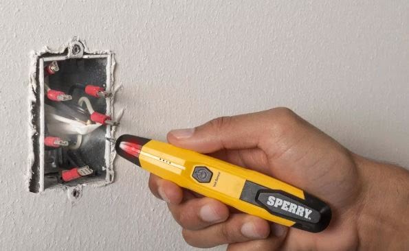
5. Polarity Testing: Verifying Correct Wiring Connections
Purpose: Polarity testing is essential to ensure that electrical connections are made correctly, especially in alternating current (AC) circuits. Incorrect wiring can lead to malfunctions in equipment and pose safety hazards.
Method: Using a polarity tester or a multimeter, this test checks the correct alignment of live and neutral wires. In AC circuits, maintaining proper polarity is crucial for the correct operation of devices.
Significance: Ensuring correct polarity is vital for the safe and efficient operation of electrical systems. Incorrect wiring can lead to equipment damage, electric shocks, and hazardous conditions.
6. Dielectric Strength Testing: Assessing Insulation Integrity
Purpose: Dielectric strength testing, also known as high-potential or hipot testing, is performed to assess the ability of insulation materials to withstand high voltages without breaking down. This test helps identify potential weaknesses in insulation.
Method: A high-voltage source is applied to the insulation for a specific duration, and the current flow is monitored. The insulation should withstand the applied voltage without allowing excessive current to pass.
Significance: Dielectric strength testing is crucial for ensuring the insulation integrity of electrical components and preventing breakdowns that could lead to equipment failure or safety hazards.
7. Functional Testing: Evaluating Equipment Performance
Purpose: Functional testing is conducted to verify whether electrical equipment performs its intended functions correctly. This type of testing is specific to the equipment being assessed and may involve various operational checks.
Method: Functional testing can vary widely based on the type of equipment. It may include simulating normal operating conditions, testing safety features, and assessing control systems.
Significance: Functional testing is essential for ensuring that electrical equipment meets the specified performance criteria. It helps identify any issues that may affect the functionality of the equipment in real-world scenarios.
8. Thermal Imaging: Detecting Overheating Issues
Purpose: Thermal imaging is a non-invasive method used to detect potential issues related to overheating in electrical systems. It helps identify hotspots caused by loose connections, overloaded circuits, or faulty components.
Method: Infrared thermography cameras are used to capture thermal images of electrical components. Hotspots are indicative of areas with increased resistance or poor connections.
Significance: Identifying overheating issues early through thermal imaging can prevent equipment damage, reduce the risk of electrical fires, and improve the overall safety and reliability of the electrical system.
9. Power Quality Testing: Ensuring Stable Voltage and Current
Purpose: Power quality testing assesses the stability and reliability of voltage and current in electrical systems. It helps identify issues such as harmonics, voltage sags, and other irregularities that can affect the performance of sensitive equipment.
Method: Various instruments, including power analyzers and oscilloscopes, are used to measure and analyze the quality of voltage and current in the system.
Significance: Maintaining good power quality is crucial for the proper functioning of electronic equipment. Poor power quality can lead to equipment malfunctions, increased energy consumption, and reduced lifespan of electrical components.
10. Ground Fault Testing: Detecting Faults in Grounded Systems
Purpose: Ground fault testing is conducted to identify faults in grounded electrical systems. It helps detect leakage currents that may occur when unintended paths for current flow are present.
Method: Using specialized ground fault testers, this test measures the current flowing to the ground. An imbalance in current indicates the presence of a ground fault.
Significance: Identifying ground faults is essential for preventing electric shock hazards and ensuring the proper functioning of protective devices in grounded systems.
FAQs
Conclusion
In conclusion, electrical testing plays a pivotal role in ensuring the safety, reliability, and efficiency of electrical systems. From the initial installation of electrical components to ongoing maintenance and troubleshooting, various testing methods are employed to identify potential issues and verify the integrity of electrical installations. Continuity testing, insulation resistance testing, and other types of testing help maintain the safety of personnel, protect equipment, and comply with regulatory standards.
Regular electrical testing is not only a proactive approach to preventing failures but also a key component in optimizing the performance of electrical systems. As technology advances and electrical systems become more complex, the importance of comprehensive testing methodologies continues to grow. Electrical engineers, maintenance personnel, and safety professionals must stay abreast of evolving testing standards and technologies to ensure the continued reliability of electrical installations in diverse applications.