 Electrical Engineering World Wiring a Brighter Tomorrow!
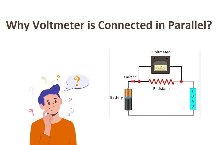
Why Voltmeter is Always Connected in Parallel?
Introduction
In the realm of electrical measurements, voltmeters are indispensable tools used to measure voltage across various components in circuits. Whether you’re a seasoned electrician, an engineering enthusiast, or simply curious about electrical instruments, understanding why voltmeters are always connected in parallel is crucial. In this article, we will explore the rationale behind this common practice and its significance in accurate voltage measurements. So, let’s dive into the world of parallel connections and voltage measurements!
Why Voltmeter is Always Connected in Parallel?
In order to comprehend why an ammeter is connected in series while voltmeter is always connected in parallel, it’s essential to grasp the fundamentals of voltage measurements. When we talk about measuring voltage, we refer to the difference in electrical potential between two points in a circuit. Voltage is typically measured using a voltmeter, which is designed to have a very high resistance.
The Importance of High Resistance in Voltmeters
The key reason for connecting a voltmeter in parallel is to ensure minimum interference with the circuit being measured. The voltmeter’s high resistance plays a pivotal role in achieving this objective. Here’s why:
- Voltmeters are constructed with a very high internal resistance, ideally infinite in an ideal voltmeter. This high resistance ensures that the voltmeter draws minimal current from the circuit during measurement. As a result, the voltmeter has a negligible effect on the circuit’s behavior, and the voltage being measured remains unaffected.
- If a voltmeter had low resistance, connecting it in parallel would allow a significant current to flow through the meter and the circuit simultaneously. This current could potentially damage the circuit or cause inaccurate readings. The high resistance of the voltmeter prevents any substantial current from flowing through it, thereby safeguarding both the circuit and the voltmeter.
Understanding Parallel Connection
Before we proceed further, let’s briefly delve into what a parallel connection means in the context of electrical circuits.
- In electrical circuits, parallel connection refers to a configuration where multiple components share the same two end-points. These components have their individual paths to the power source, and the potential difference across each component remains the same. In other words, the voltage measured across parallel components is constant, making it an ideal arrangement for voltmeter connections.
Using a Voltmeter in Series vs. Parallel
Now that we have a basic understanding of parallel connections let’s compare the use of voltmeters in series and parallel arrangements.
- In a series connection, a voltmeter is placed in-line with the component whose voltage we want to measure. The voltmeter acts as an additional resistance in series with the component, altering the total resistance and affecting the voltage drop across the component. As a result, the series connection is impractical for most voltage measurements.
- In contrast, the parallel connection offers significant advantages. By connecting the voltmeter in parallel to the component being measured, the voltmeter doesn’t interfere with the current flow in the circuit. It only measures the potential difference across the component while drawing minimal current. This parallel arrangement ensures accurate voltage measurements without disturbing the circuit’s behavior.
The Ideal Voltmeter: Zero Current Draw
- In an ideal voltmeter, the internal resistance is infinite, resulting in zero current draw from the circuit under measurement. Such a voltmeter would display the precise potential difference across the component being tested. Although achieving an ideal voltmeter is practically impossible, modern digital voltmeters come remarkably close to this ideal with their high input impedance.
Applications of Parallel Voltmeter Connections
- Parallel connections for voltmeters find widespread applications in the field of electronics and electrical engineering. Some of the key applications include:
- Troubleshooting circuits to identify faulty components without disturbing the original circuit behavior.
- Testing batteries to determine their voltage and state of charge accurately.
- Measuring voltage drops across various components in complex circuits to ensure they operate within the specified limits.
- Analyzing power supplies to ensure consistent and stable output voltages.
Common Misconceptions About Voltmeter Connections
- Despite the straightforward concept of connecting voltmeters in parallel, there are several misconceptions surrounding their usage. Let’s address some of the most common misconceptions:
- Misconception 1: Connecting a voltmeter in series gives more accurate readings. This is not true because series connections alter the circuit’s behavior, leading to inaccurate readings.
- Misconception 2: Voltmeters with lower resistance provide more accurate results. In reality, a voltmeter with higher resistance is preferred as it minimizes current draw and disturbance to the circuit.
- Misconception 3: Parallel connections are only suitable for low-voltage measurements. Parallel connections are suitable for measuring voltages across a wide range, including both low and high values.
FAQs
Is it safe to connect a voltmeter in parallel to a live circuit?
Yes, it is safe to connect a voltmeter in parallel, given that the voltmeter’s high resistance ensures minimal current draw.
Can I measure AC voltage using a parallel voltmeter connection?
Absolutely! Parallel voltmeter connections work well for both DC and AC voltage measurements, provided the voltmeter is appropriately rated.
Does the length of the voltmeter leads affect the measurements?
Yes, for accurate readings, keep the voltmeter leads as short as possible to minimize any additional resistance and interference.
Why are digital voltmeters preferred over analog voltmeters?
Digital voltmeters generally have higher input impedance and offer better accuracy and readability compared to analog counterparts.
Can I use a multimeter as a voltmeter in parallel?
Yes, multimeters often include a voltmeter function that can be used in parallel connections for voltage measurements.
Can connecting a voltmeter in series damage the component being tested?
In some cases, a series voltmeter connection can alter the circuit and potentially damage sensitive components. Therefore, parallel connections are the preferred choice.
Conclusion
In conclusion, connecting a voltmeter in parallel is a fundamental practice in electrical measurements. By maintaining a high internal resistance, the voltmeter ensures minimal interference with the circuit under measurement. This parallel arrangement allows for accurate and reliable voltage readings without affecting
the circuit’s behavior. It offers a safe and effective way to measure voltage across components in various applications, including troubleshooting circuits, testing batteries, and analyzing power supplies.
When using a voltmeter, always remember to connect it in parallel to avoid altering the circuit and obtaining inaccurate readings. The high resistance of the voltmeter guarantees minimal current draw and protects both the circuit and the instrument.
In today’s market, digital voltmeters have become increasingly popular due to their higher input impedance and improved accuracy. These modern instruments provide clear and precise readings, making them ideal for a wide range of voltage measurements.