 Electrical Engineering World Wiring a Brighter Tomorrow!
Potentiometer Circuit Diagram and Working
Introduction
Potentiometers, also known as variable resistors, are a fundamental component in electronic circuits. They are used to control the flow of electrical current in a circuit by altering the resistance of the circuit. Potentiometers are widely used in various applications, such as volume controls in audio systems, speed controls in electric motors, and dimmer switches in lighting systems. In this article, we will discuss the circuit diagram and working principle of potentiometers.
Definition
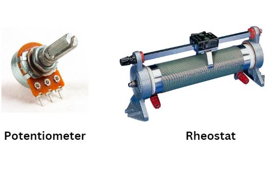
A potentiometer or rheostat or variable resistor is an instrument commonly utilized in a specialized field so as to decide the difference of electrical potential between two electrical terminals. The potential difference is what is usually known as voltage. It is basically a variable resistance used to control power to a load and you are right about the wiring.
Difference between variable resistor and potentiometer
A rheostat utilizes the slider and one other terminal are utilized. A potentiometer utilizes each of the three terminals, empowering a variable voltage or sign to be tapped off from the slider.
How does a potentiometer work?
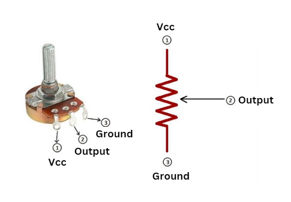
A potentiometer has a basic activity, has a variable resistance at each end and a third association with a sliding control, which will enable us to increment or abatement the resistance itself . The reason for this is to accomplish a variable incentive between associations, which we can control ourselves.
To know top to bottom how a potentiometer functions , it is essential to know its parts and what capacity every one of them satisfies. It essentially comprises of a variable resistor , which changes its incentive as the present increments.
This resistor has three terminals to which the voltage to be estimated is associated. By shifting the resistance, the potential difference between the terminals changes. Along these lines the estimation of the voltage is dictated by the variety of the resistance.
Potentiometer Types
There are various sorts of potentiometers, and these characterizations rely upon the variety of their resistance , the kind of control and (in innovation) the innovation of the equivalent.
1- Potentiometer as indicated by varieties in resistance
Direct potentiometer:
Where the resistance fluctuates straightly to the variety of the point that the resistance was changed.
Logarithmic potentiometer :
The resistance changes relying upon the edge however this time in an exponentially opposite way.
Sinusoidal potentiometer :
It shifts relying upon the point sine.
Antilogarithmic potentiometer:
shifts exponentially at the point of rotation.
2- Potentiometer as indicated by control type
Rotational potentiometer :
They are controlled by turning a hub. They are enduring and occupy little room.
Sliding Potentiometer :
Controlled by running a cursor in a straight line. Extremely utilized in realistic equalizers.
Various Potentiometer :
They have coaxial tomahawks. Along these lines they consume considerably less space.
3- Digital potentiometer
They are those whose activity operates like an analog potentiometer through a coordinated circuit, is described by more prominent precision.
Uses of a potentiometer
The potentiometers are utilized for some electrical and electronic gadgets. They can be connected both to play out an order activity, that is, to alter any condition, or as a modification work, that is, recognize any abnormality and right. Here are a few models:
Sound control: The volume of a music framework is controlled through a potentiometer.
Lighting: When controlling the splendor force.
Control frameworks: It is exceptionally basic to discover it in control frameworks so as to go about as measurers of some specific variable.
Conclusion
In conclusion, potentiometers are an essential component in electronic circuits. They offer a simple and effective way to control the flow of electrical current in a circuit by varying the resistance of the circuit. The potentiometer circuit diagram is straightforward and easy to understand, making it a popular choice for beginners in electronics. With its versatility and reliability, the potentiometer will continue to be an important tool for engineers and hobbyists alike.