 Electrical Engineering World Wiring a Brighter Tomorrow!
Oscilloscope Guide
Introduction
Definition and purpose of an oscilloscope
An oscilloscope, often referred to as an “scope” or “o-scope,” is an electronic test instrument used to visualize and analyze electrical waveforms. It displays voltage signals in the time domain, allowing engineers and technicians to observe the characteristics of various electronic signals. Oscilloscopes are essential tools in electrical engineering, electronics design, and troubleshooting, as they provide valuable insights into signal behavior and enable accurate measurement and analysis.
Importance in electrical engineering and troubleshooting
Oscilloscopes play a crucial role in electrical engineering and troubleshooting for several reasons:
1. Waveform Visualization: Oscilloscopes enable the direct visualization of electrical signals, making it easier to understand and analyze complex waveforms.
2. Signal Integrity Analysis: By observing voltage waveforms, engineers can assess the integrity of signals, detect abnormalities, and identify potential issues like distortions, noise, or signal anomalies.
3. Time-Domain Analysis: Oscilloscopes provide a detailed representation of signal characteristics in the time domain, allowing engineers to measure parameters such as voltage amplitude, frequency, rise time, pulse width, and timing relationships.
4. Troubleshooting and Debugging: When diagnosing electrical circuits, oscilloscopes help identify faulty components, signal path issues, timing errors, and signal distortions, aiding in effective troubleshooting and debugging.
5. Design and Development: Oscilloscopes are essential tools for designing and prototyping electronic circuits, as they help engineers validate circuit behavior, analyze signal interactions, and fine-tune circuit parameters.
Basic Principles
Definition of voltage and time domains
The voltage domain represents the amplitude or strength of an electrical signal. It is typically measured in volts (V) and displayed along the vertical axis of an oscilloscope’s screen. The voltage domain provides information about signal amplitude, peak-to-peak voltage, and voltage levels at different points in time.
The time domain represents the temporal behavior of an electrical signal. It is measured in seconds (s) and displayed along the horizontal axis of an oscilloscope’s screen. The time domain provides information about the duration of a signal, rise and fall times, and timing relationships between different events within a waveform.
Graphical representation of electrical signals
Oscilloscopes display electrical signals graphically using a cathode-ray tube (CRT) or a digital display. The graphical representation allows users to observe how voltage varies with respect to time, enabling analysis of signal characteristics such as amplitude, frequency, phase, and distortion.
Working principle of a cathode-ray tube (CRT)
A cathode-ray tube (CRT) is a key component of analog oscilloscopes. It works based on the principle of electron beam deflection. The CRT consists of an electron gun that emits a focused electron beam, which is accelerated and directed towards a phosphor-coated screen. The electron beam is deflected vertically and horizontally by applying voltages to two sets of deflection plates. When the electron beam strikes the phosphor screen, it causes the phosphor to emit light, creating a visible trace that represents the electrical waveform being analyzed.
Components of an Oscilloscope
Vertical Amplifier
The vertical amplifier is responsible for amplifying and conditioning the input signal before it is displayed on the oscilloscope screen. The vertical amplifier typically consists of several stages, including a pre-amplifier, gain control circuitry, and signal conditioning components. It amplifies the voltage signal and provides options to adjust gain and sensitivity to accommodate different signal levels. Additionally, the vertical amplifier allows for attenuation and selection of probe options to match the input impedance and voltage range of the oscilloscope.
Horizontal Amplifier
The horizontal amplifier controls the timebase and horizontal deflection of the electron beam, determining the time scale and the width of the displayed waveform. It generates a ramp or sawtooth waveform, which controls the horizontal deflection plates of the CRT. The timebase generator produces a repetitive sawtooth waveform, and by adjusting the time scale control, users can control the time period represented on the screen.
Trigger Circuit
The trigger circuit is responsible for initiating the display of the waveform on the oscilloscope screen. It ensures that the waveform is stable and stationary, enabling repetitive waveform observation. The trigger circuit detects specific signal characteristics, such as voltage level or slope, and triggers the timebase to start the horizontal sweep when the selected trigger condition is met.
Display
The display section of an oscilloscope consists of a cathode-ray tube (CRT) or a digital display, where the waveform is visually presented. In analog oscilloscopes, the CRT displays the waveform as a luminous trace on a phosphor-coated screen. Digital oscilloscopes utilize LCD or LED screens to display the waveform digitally. The display section may include controls for intensity adjustment, focus control, and additional features such as persistence or waveform storage.
Operating Modes
Single Trace Mode
In single trace mode, the oscilloscope displays a single waveform at a time. This mode is useful when analyzing and capturing a single signal of interest. The trigger settings determine when the oscilloscope begins displaying the waveform, ensuring that it remains stable on the screen. Single trace mode is commonly used for general waveform observation and troubleshooting.
Dual Trace Mode
Dual trace mode enables the simultaneous display of two waveforms on the oscilloscope screen. This mode is beneficial when comparing two signals, such as input and output waveforms, or analyzing signal interactions. Dual trace mode provides separate controls for each channel, allowing users to adjust settings such as vertical position, gain, and coupling for each waveform independently.
XY Mode
XY mode, also known as X-Y mode or vector mode, allows the oscilloscope to plot one signal against another, creating a graphical representation of their relationship. This mode is commonly used in vector analysis, where one signal is applied to the vertical deflection plates, and another signal is applied to the horizontal deflection plates. It enables the visualization of phase relationships, Lissajous patterns, and the assessment of signal distortions or anomalies.
Additional Features and Functionality
Probe compensation and calibration
Oscilloscope probes, used to connect the test points on a circuit to the instrument, often require compensation to ensure accurate measurements. Many oscilloscopes offer probe compensation features, allowing users to adjust the probe’s capacitance and resistance to match the oscilloscope’s input impedance.
Cursors and measurements
Oscilloscopes provide cursor functions to measure various parameters of the displayed waveform, such as voltage levels, time intervals, rise and fall times, and frequency. Cursors allow users to make precise measurements directly on the screen, facilitating analysis and troubleshooting.
Persistence and waveform storage
Persistence is a feature that determines how long a trace remains visible on the oscilloscope’s screen. It can be adjusted to display the persistence of the waveform, allowing users to observe the behavior over time. Some oscilloscopes also offer waveform storage capabilities, enabling the capture and storage of waveforms for later analysis or comparison.
Applications of Oscilloscopes
Signal analysis and troubleshooting
Oscilloscopes are extensively used in signal analysis and troubleshooting scenarios. They help engineers
identify and resolve issues such as distortions, noise, glitches, and timing errors in electronic circuits and systems. By visualizing and analyzing waveforms, engineers can diagnose faults, locate defective components, and verify proper signal functioning.
Circuit design and prototyping
Oscilloscopes are invaluable tools for circuit design and prototyping. Engineers use oscilloscopes to validate circuit behavior, assess the performance of electronic components, and verify signal integrity. Oscilloscopes aid in optimizing circuit design, adjusting parameters, and ensuring the desired functionality and reliability of the circuit.
Frequency and amplitude measurement
Oscilloscopes provide accurate frequency and amplitude measurements of electrical signals. By analyzing waveforms, engineers can determine the frequency of periodic signals, identify harmonics, measure signal amplitudes, and assess signal quality.
Pulse and timing analysis
Oscilloscopes are widely employed in pulse and timing analysis applications. They enable precise measurement and evaluation of pulse width, rise time, fall time, duty cycle, and timing relationships between different signals. Pulse and timing analysis is crucial in digital circuit design, communication systems, and high-speed data transmission.
Choosing the Right Oscilloscope
Bandwidth and sampling rate considerations
When selecting an oscilloscope, bandwidth and sampling rate are essential factors to consider. The bandwidth determines the range of frequencies that the oscilloscope can accurately capture and display. The sampling rate defines the number of samples per second that the oscilloscope can acquire. Choosing an oscilloscope with appropriate bandwidth and sampling rate ensures accurate waveform capture and fidelity.
Number of channels and vertical resolution
The number of channels required depends on the complexity of the signals being analyzed. Oscilloscopes are available with single, dual, or multiple channels, allowing simultaneous observation of multiple waveforms. Vertical resolution refers to the number of voltage levels that an oscilloscope can display. Higher vertical resolution provides finer detail and more accurate measurements.
Additional features and compatibility
Consideration should be given to additional features and compatibility requirements. This includes the availability of advanced triggering options, analysis capabilities, connectivity options (such as USB or Ethernet), and compatibility with software or external devices for data logging and analysis.
FAQs
What is an oscilloscope in electrical?
An oscilloscope is an electronic test instrument used to visualize and analyze electrical waveforms. It displays voltage signals in the time domain, allowing engineers to observe and measure various characteristics of electrical signals.
What is the application of oscilloscope in electrical engineering?
Oscilloscopes have numerous applications in electrical engineering, including signal analysis, troubleshooting, circuit design, frequency measurement, amplitude measurement, pulse and timing analysis, and more. They are essential tools for engineers to validate circuit behavior, diagnose faults, and ensure signal integrity.
What is the use of an oscilloscope instrument?
The primary use of an oscilloscope is to display and analyze electrical waveforms. It helps engineers visualize and measure voltage signals, observe signal behavior over time, and make accurate measurements of signal parameters such as amplitude, frequency, rise time, and timing relationships. Oscilloscopes are indispensable in electronics, electrical engineering, and related fields.
What is the working principle of an oscilloscope?
The working principle of an oscilloscope involves amplifying and conditioning the input signal, generating a timebase for horizontal deflection, triggering the display of the waveform, and deflecting an electron beam to create a visible trace on a screen. By controlling the vertical and horizontal deflections, the oscilloscope creates a graphical representation of the input waveform.
What are three applications in which an oscilloscope is used?
Three applications of oscilloscopes are:
- Troubleshooting electrical circuits and systems
- Designing and prototyping electronic circuits
- Analyzing and measuring signal characteristics, such as frequency, amplitude, and timing relationships.
Do electrical engineers use oscilloscopes?
Yes, electrical engineers extensively use oscilloscopes in their work. Oscilloscopes are essential tools for electrical engineers to analyze and troubleshoot electrical circuits, validate circuit designs, measure signal characteristics, and ensure proper functioning of electronic systems.
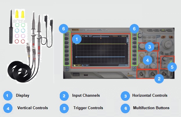
What are the three main control sections of an oscilloscope?
The three main control sections of an oscilloscope are:
- Vertical controls: Adjust the vertical position, gain, and sensitivity of the displayed waveform.
- Horizontal controls: Set the timebase, control the time scale, and adjust the horizontal position of the waveform.
- Trigger controls: Define the triggering conditions, such as trigger source, trigger level, and trigger slope, to initiate the display of the waveform.
What is the introduction of an oscilloscope?
The introduction of an oscilloscope typically includes defining its purpose as an electrical instrument used for visualizing and analyzing electrical waveforms. It highlights the importance of oscilloscopes in electrical engineering, troubleshooting, and their role in providing valuable insights into signal behavior and accurate measurements of various signal parameters.
What are the main controls of an oscilloscope?
The main controls of an oscilloscope include:
-
- Vertical controls: Adjust the position, gain, and sensitivity of the displayed waveform.
- Horizontal controls: Set the timebase, adjust the time scale, and control the horizontal position of the waveform.
- Trigger controls: Define the triggering conditions, including the trigger source, trigger level, and trigger slope, to initiate the display of the waveform. Additional controls may include intensity, focus, probe compensation, and cursor controls for making measurements on the displayed waveform.
Conclusion
Oscilloscopes are essential tools in electrical engineering and troubleshooting. They allow engineers to visualize, analyze, and measure electrical waveforms accurately, aiding in circuit design, troubleshooting, and signal analysis. Oscilloscopes provide valuable insights into signal behavior, enabling engineers to detect and resolve electrical issues efficiently.
Oscilloscope technology continues to advance, with increasing bandwidth, higher sampling rates, and enhanced analysis capabilities. Digital storage oscilloscopes (DSOs) and mixed-signal oscilloscopes (MSOs) are becoming more prevalent, offering improved functionality and integration with digital systems. Additionally, remote access and control capabilities, as well as cloud-based waveform analysis, are emerging trends in oscilloscope technology, allowing for greater flexibility and collaboration in electronic design and troubleshooting.